
This post will focus on checking the iqLED Alpha-A5 RF controller after factory assembly.
This publication is intended for manufacturers and factories only.
If you are a retail user, then DO NOT USE THESE MATERIALS!!!
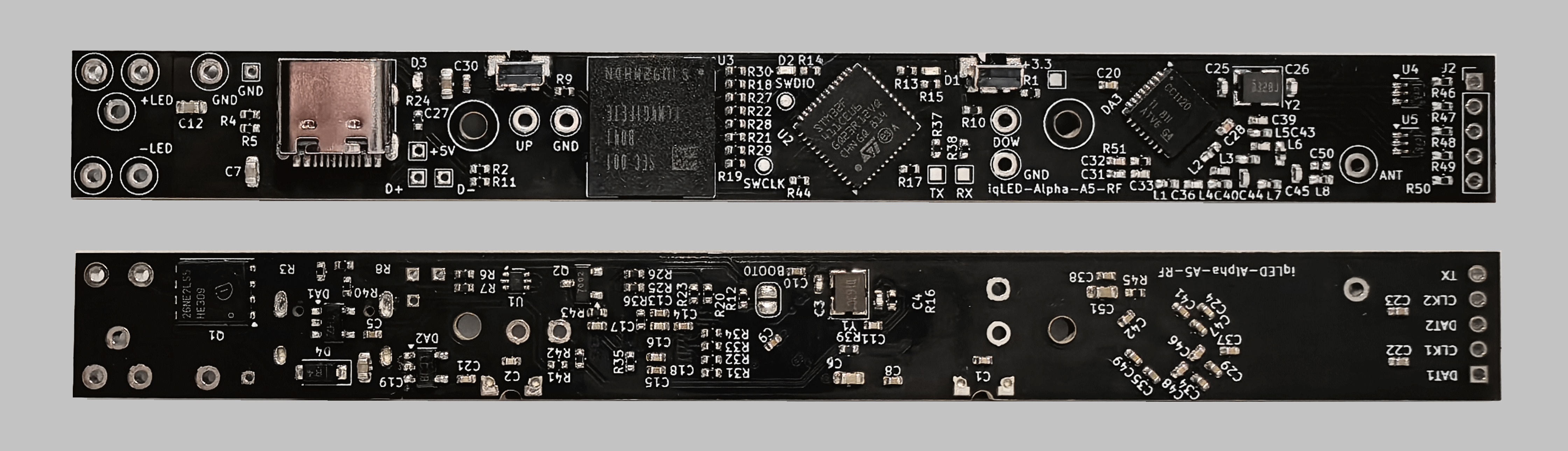
Before using the controller, carefully inspect the product for defects, deep scratches, "sticky", etc. All components should sit clearly in their places without displacement, as in the photo below.
Flashing test firmware to the microcontroller
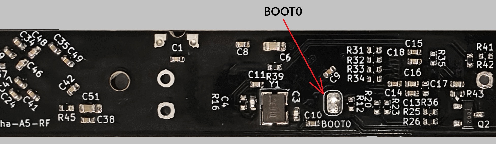
1.0 Use your soldering iron and solder to make a solder bridge (a small solder connection) at BOOT0 — see the picture below for reference:
1.1 To flash the test firmware, first install the STM32 Cube Programmer software as shown in the video below.
download STM32CubeProgrammer /248 MB/: https://www.iqled.org/soft/stm32cubeprg ... 2-20-0.zip
download this video: https://www.iqled.org/Video/A5-RF/STM32 ... rammer.mp4
or watch it on Vimeo:
1.2 The controller power connection diagram is shown below.
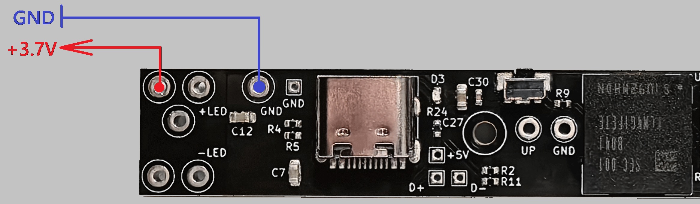
1.3 Connect the power clips of the power supply unit to the A5‑RF controller, then press the Power On button on the power supply unit. Use a laboratory power supply with a voltage of +3,7 V and a current limit of 100 mA.
download this video: https://www.iqled.org/Video/A5-RF/A5-RF-Power.mp4
or watch it on Vimeo:
1.4 Connect the USB-C flex cable to your computer and flash the firmware.
download Check Firmware https://www.iqled.org/firmware/iqLED-Al ... -Check.zip
download this video: https://www.iqled.org/Video/A5-RF/Flash_firmware.mp4
or watch it on Vimeo:
1.5 After successfully flashing the microcontroller, disconnect USB-C, turn off the power of the laboratory power supply, disconnect the clips, as shown in the video below.
download this video: https://www.iqled.org/Video/A5-RF/A5-RF-Disconnect.mp4
or watch it on Vimeo:
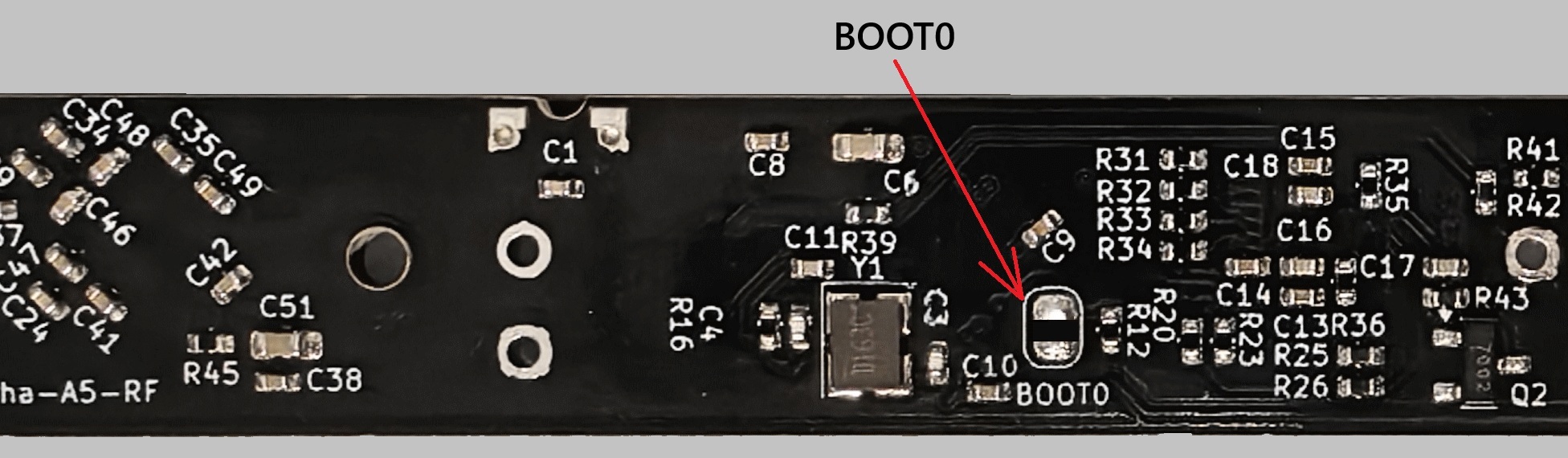
1.6 Using a soldering iron, remove the solder bridge (small solder joint) on BOOT0 - see the picture below for reference:
1.7 Connect the iqLED Alpha-A5 RF to USB-C on your PC or power bank to provide power. Use an insulated pusher (a small plastic or wooden stick) to test the buttons and LED indicators.
download this video: https://www.iqled.org/Video/A5-RF/A5-RF ... uttons.mp4
or watch it on Vimeo:
1.8 Make sure the Green LED (D3) indicator is working properly. It should light when the USB is connected.
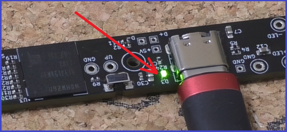
1.9 Check Radio. To check, you need to use a couple of controllers iqLED-Alpha-A5-RF. Check the UP and DOWN buttons. Watch the reaction of the green and red LED. Since a pair of controllers are connected via a radio channel, when the buttons on one controller are manipulated, the red and green indicators should be ON state on the adjacent controller.
download this video: https://www.iqled.org/Video/A5-RF/A5-RF-Radio-Test.mp4
or watch it on Vimeo:
Congratulations! The main part of the check is completed!!!